Cool Engineering

Info on some cool engineering projects

Friday, June 16, 2006

Wireless working ... well almost


With some breathing space of a week between exams I decided to try and get the wireless link working for our project. Pondering on this I'm not sure why - the spec says comms interfaces are Wades job, but with his reluctance to use serial communication having these archaic Apples :) without serial ports I guess the lot fell to me.
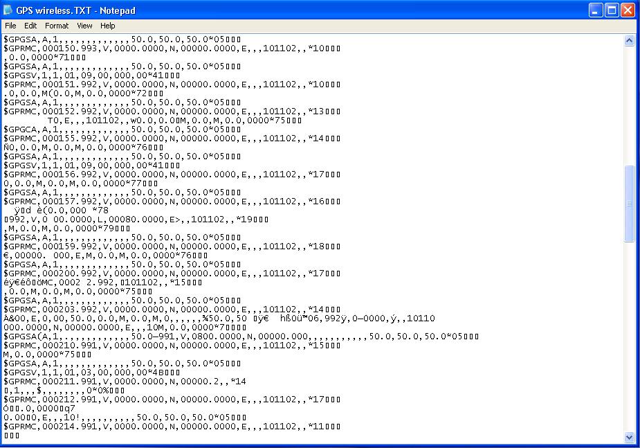
After a meeting with our supervisor, our hopes of getting this little module to do 100m were somewhat attenuated after past years students best efforts were in the order of 1m. After a day of toil and experimentation I have finally got some results. At 1m I had GPS data transmitting at 4800bps. Unfortunately the data is quite noisy with lots of junk in there. I think Wade will have to implement error correcting codes like hamming codes to get this to work reliably. The other consideration is that we were not doing this properly using Manchester encoding and so would have skew problems. With Manchester encoding I'm expecting to get around 50m - hopefully.
One weird side affect of all this was that when the receiver (not the transmitter!!) was powered up horizontal lines were seen on the TV downstairs. Possibly they run on the same power circuit, but I still think this is really weird - It shouldn't be transmitting (and therefore interfering) anything. Oh well - time for Wade to implement Manchester encoding :)

Wednesday, June 07, 2006

GPS Antenna Hacking


Ok we have discovered a small (or rather heavy) problem with our grand plan. Most of the avionics equipment onboard the plane is both tiny and light (eg. GPS reciever ~ 12g). Not so with the $30 GPS antenna I purchased of eBay. With a moulded plastic case and metal base with magnets this was both large (see pic) and heavy (~90g). The aim of the project is to get the avionics equipment under 100g, so an antenna taking up 90% of this allowance was just not on.


So onto the hacking: In the second pic you can see the antenna with the case removed. Next I removed the heavy metal base (with built in magnets). The cable on the antenna was 5m in length (about 4.9m too long). After some fine soldering work we end up with figure 3 - much smaller and only ~17g. This is not really the way to do things for mass production, but as a stopgap meaure works nicely. Hopefully the antenna is still operations - I will know later today.

Ground - which one?

Aside from our main UAV project we have recently been sidetracked with several smaller hardware projects, like our Advanced Digital Design project.
We did at least double what the spec set out and created an RS-232 based network system with error detection and a bridge board. My part was the bridge board and for some reason I could only get one of the client boards to properly communicate with it.
After several hours of pain, I realised the solution was really simple. The primary serial connection incorparated a ground connection so the boards were grounded to the same potential. The auxillary serial connection had no ground so the boards could have been at entirely different ground levels. After quickly connecting ground connections with a piece of wire everthing worked a treat.