Cool Engineering

Info on some cool engineering projects

Saturday, May 27, 2006

How did you get the camera to take photographs?

Ok here is an excellent question - how do I actually control the camera.
Basically there are 3 different methods of controlling the camera and 2 methods of choosing when to take photographs.
Methods of controlling the camera:
a) have a servo arm depress the shutter button
b) connect a relay across the switch terminals and have a trigger circuit actuate it
c) connect a trigger circuit directly to the switch terminals
a) is the low tech method and seems to be less reliable as it relies on mechanical contact. BTW I'm an electronic engineer - not a mechanical one - maybe this also guided my decision. This method is also the heaviest.
b) This was my old setup. Basically the same as (c) but using a relay instead of directly modifying logic levels on the circuit
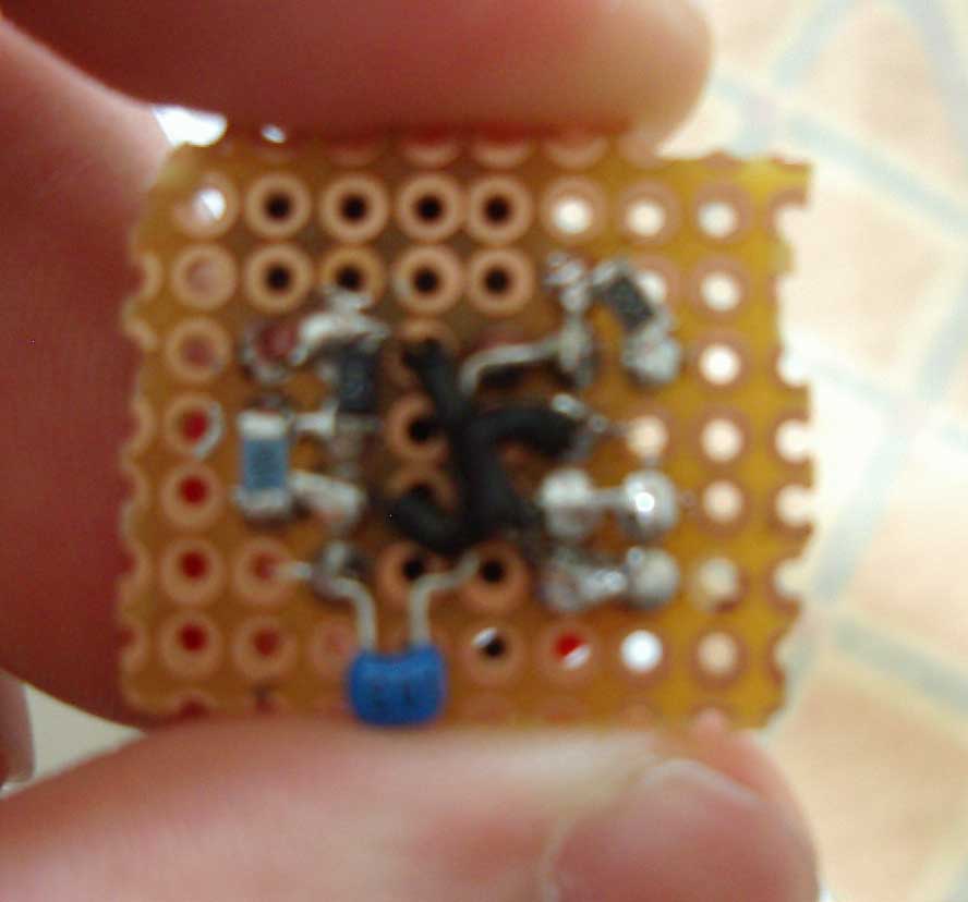
c) My new setup. Took a bit of trial and error to get working (need to connect the output of the trigger circuit up the correct way. This is the lightest solution (shown in pic).
For (b) and (c) the camera needs to be opened up and wires soldered across the switch terminals. Extra care needs to be taken to ensure the internals (lenses and such) of the camera are not damaged in this process. At this stage I also stripped most of the unrequired stuff of the camera off - (cover, ect.).

To actually trigger the camera there are 2 main methods:
a) Using an additional channel on the controller
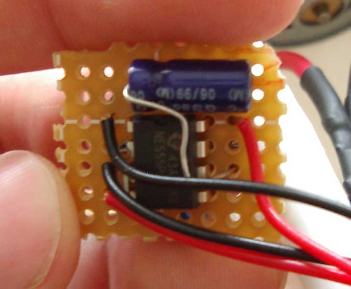
b) Using a timer circuit.
a) I have a circuit lying around somewhere that should do this - I just couldn't find it. It basically takes the receiver output (which is a PWM setup to drive servos) and coverts it to a logic 1 or 0 depending on the PWM width. This is a better method as the user has complete control of when photos are to be taken.
b) This is the most simple method and one I readily had a circuit available for. I have set the camera up to take a photo every 15s or so. This can be a bit hit and miss as from the ground I'm not sure when photos are actually being snapped. The circuit diagram for this is shown on the right. Connecting a 100nF cap from supply to ground should help to stabilise the input supply voltage).

Wednesday, May 17, 2006

More aerial photos


Ok, we have a presenation about the UAV concept on Friday and decided to go out and get some fresh and really nice aerial photos from the plane. After strapping a 2MP camera to the plane and sending it up (and fetching it from the tree once) we have a total of 44 photographs - some from the ground. Of these 44 about 20 look really good (crisp and actually of something).
One photo is attached for your viewing pleasure - the rest will make my other website soon.

Plane Photos + Logo


The last few weeks have consisted of heaps of paperwork, presentations and minor assignments.
The first picture is my plane - fitted out with the onboard video camera. We (Wade) are in the process of designing a new antenna as the signal cuts out when we turn away from the base station.
The second pic is our logo for a marketing exercise. We are now known as AE Robotics (another one of my suggestions). The AE stands for 'Aerospace Engineering'. We have discussed the possibly (in business plans) of branching out into autonomous submarines ect. Fortunately the business name still works as 'Aquatic Engineering'.

Wednesday, May 03, 2006

More sucess amidst holdups

I haven’t really done lots of project work over the last week or two, despite thinking about the project lots. The major cause of this temporary hold-up on project work has been other project work. Last Wednesday I submitted my traffic controller project, which was basically a project designed to simulate the traffic light controls at intersections - with pedestrian crossings and all. It seemed that everything went OK and I managed to get 10/10 for the demonstration - hopefully the report is received equally as well. Besides this and other uni project taking up lots of time I have been applying for graduate job positions and already have a number of interviews to attend - a process which really eats up time.
In terms of success it seems that Wade is making some progress on the SD card interface (I better adjust the Gantt chart as this was scheduled to be finished about a month ago :)), and it seems I have finally managed to find some cable to suit the tiny connector mentioned in the last post. Our supervisor suggested hacking up an only EIDE cable (which has a smaller pitch than the standard IDE cable and should fit perfectly.